C-Type Sealing Coupling
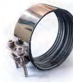

KELI supplies stainless steel couplings and clamps for joining socketless cast iron pipes and fittings. Selection is based on pipe OD/DN, coupling design, seal requirements and installation conditions.
KELI two-segment grip collars provide axial restraint at compatible cast iron drainage joints. Installed around a separately specified sealing coupling, the collar helps resist separation of the pipe ends under internal pressure. The sealing coupling and gasket provide the seal; the grip collar provides restraint.
This series covers DN50, DN80, DN100, DN125 and DN150, with two 180° segments and grade 8.8 bolts. Select the complete pipe, sealing coupling and grip-collar assembly for the project conditions.
| DN | Drawing D (mm) | Drawing L (mm) | Torque per bolt (Nm) | Bolt size | Hydrostatic end-thrust test target (bar) |
|---|---|---|---|---|---|
| 50 | 111 | 72 | 20 | M8 × 30 | 10 |
| 80 | 136 | 72 | 20 | M8 × 30 | 10 |
| 100 | 172 | 82 | 25 | M10 × 35 | 10 |
| 125 | 202 | 96 | 25 | M10 × 35 | 8 |
| 150 | 226 | 96 | 25 | M10 × 35 | 8 |
D and L refer to the grip-collar drawing dimensions; D is not the pipe outside diameter. Confirm pipe OD, tolerance, coupling clearance and the current assembly drawing before selection. DN80 must be matched by actual pipe OD rather than automatically substituted for DN75. These dimensions and torque values apply to this two-segment series only; other catalogue clamp designs have separate schedules.
Pressure selection: 10 bar for DN50–DN100 and 8 bar for DN125–DN150 are KELI internal hydrostatic end-thrust verification targets for the identified assembly. They are not a universal working-pressure rating or a claim that every batch has been pressure tested. Request the applicable model-specific test documentation and confirm the permitted operating conditions for your project.
Specify the inspection file for the selected model: drawing and revision, D/L and fit checks, grip-tooth condition, bolt size and grade, thread integrity, surface protection, marking and traceability. For pressure restraint, request results for the complete pipe, seal, coupling and collar combination, including test pressure, duration, axial movement, leakage and post-test condition.
Rainwater, soil drainage, backwater and pumped-discharge applications require separate checks of pressure, temperature, medium, pressure transients and pipe supports. Confirm compatibility and service limits before installation.
Request a grip collar drawing and quotationTechnical documents
| Configuration | Standard or reinforced coupling/clamp, confirmed by application. |
|---|---|
| Size | Confirm pipe OD or DN and matching size range. |
| Metal components | Band, housing and fastener material grade must be stated in the RFQ. |
| Seal | Confirm elastomer material and service conditions. |
| Installation | Tightening torque and instructions are confirmed for the selected model. |
| Documents | Specify testing, approval and traceability requirements. |
Selected for compatible socketless cast iron drainage systems. State the applicable EN 877 system requirement, pipe OD, environment and approval needs.
Labelled cartons and export-suitable outer packaging by model and size. Quantity per carton, palletisation and shipping marks are agreed before production.
MOQ and delivery depend on size mix, material, seal, fastener configuration, packaging and quantity. Current lead time is quoted after model confirmation.
Pipe DN/OD · coupling model · band/fastener/seal requirements · quantity by size · standard · packaging · destination · requested delivery date.
Specify both the sealing joint and any required axial restraint. A coupling and a reinforcing or grip clamp perform different functions; confirm the complete assembly for the installation.
| Item | What the buyer should supply or request |
|---|---|
| Joint dimensions | Pipe and fitting outside diameters, tolerances and the selected coupling's allowable range. |
| Metal parts | Required stainless-steel grade for the band, housing and fasteners, plus the installation environment. |
| Elastomer seal | Wastewater composition, operating temperature and specified seal material; confirm suitability for the selected model. |
| Restraint | Required restraint arrangement and project design conditions. Do not transfer a pressure rating between different products or assemblies. |
| Installation | Model-specific drawing, tightening torque, tightening sequence and inspection instructions. |
The current catalogue includes Grip E and a Comex enhanced clamp. The enhanced-clamp table lists nominal sizes 50, 75, 100, 125, 150, 200, 250 and 300 mm. Ask KELI to confirm the matching drawing, material and application before ordering.
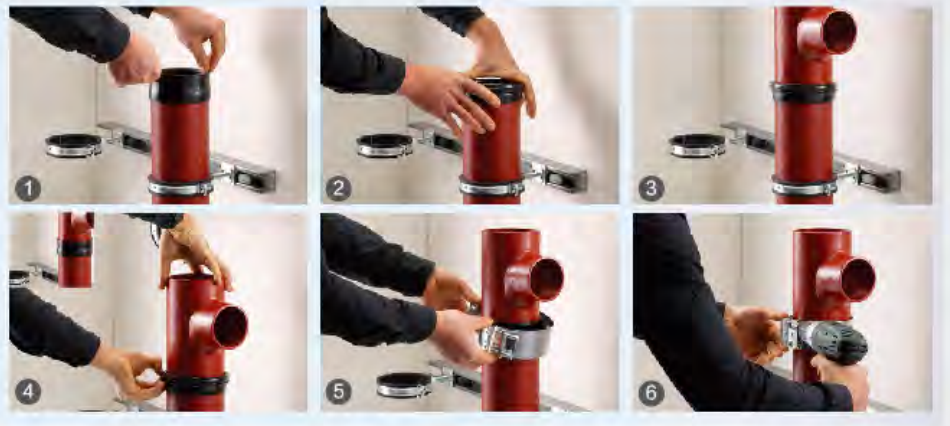
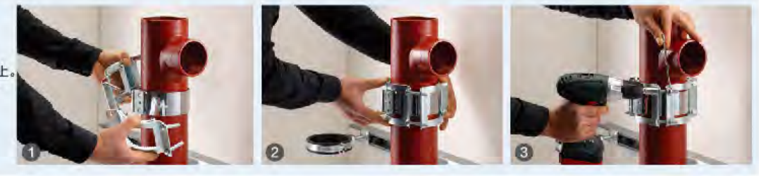
Before assembly, check pipe ends, alignment, the seal and metal components. Use the selected product's installation instructions and specified torque; support and restraint must follow the project design. Record the product model, size and inspection outcome for handover.
The published EN 877 certificate lists cast iron pipes and fittings. Coupling-specific approval, pressure and performance evidence must be checked separately for the selected assembly.
KELI product and technical guide (PDF)Installation checklist and technical resourcesRequest a coupling drawing and quotation
A seal limits leakage; axial restraint limits separation of the pipe ends. These are separate functions. A leak-tight joint is not automatically a restrained joint, and an external grip collar does not by itself provide a watertight seal.
| Catalogue family | Listed DN sizes | Function | Selection conditions |
|---|---|---|---|
| Type A | 50, 75, 100, 125, 150, 200, 250 | Rubber-ring sealing connection | Match pipe OD and sealing sleeve; confirm the restraint arrangement if axial loads are present. |
| Type C | 50, 70, 75, 100, 125, 150, 200 | Rubber-ring sealing connection | Confirm the coupling width, seal, bolt access and assembly compatibility. |
| Type W | 50, 75, 100, 125, 150 | Sealing assembly shown with toothed construction | Confirm the exact model drawing and tested axial resistance; a toothed design alone does not establish a pressure rating. |
| Convex enhanced clamp | 50, 100, 150 | External axial restraint / grip | Fit over a compatible, already installed sealing coupling; it does not replace the rubber seal. |
| Flat enhanced clamp | 50, 75, 100, 125, 150, 200, 250, 300 | External axial restraint / grip | Confirm the coupling envelope, pipe surface, bolt arrangement and required axial load for the complete assembly. |
Source: archived KELI catalogue, printed pages 44–45. These family names identify the catalogue designs, not interchangeable pressure classes. Confirm current availability, material grade, gasket compound and the approved assembly drawing.
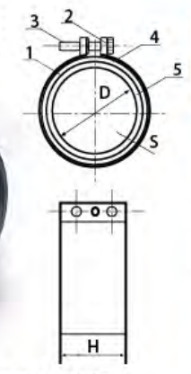
| Type A | Catalogue H = 54 mm; steel-band thickness 0.65 mm; reference mass 0.22 kg. |
|---|---|
| Type C | Catalogue H = 55 mm; steel-band thickness 0.5 mm; reference mass 0.25 kg. |
| Type W | Catalogue H = 47.5 mm; steel-band thickness 0.5 mm; reference mass 0.20 kg. |
| Convex enhanced clamp | Catalogue H = 87 mm; reference mass 1.12 kg. |
| Flat enhanced clamp | Catalogue H = 82 mm; steel-band thickness 2.5 mm; reference mass 1.00 kg. |
H is the dimension labelled in the corresponding catalogue drawing; use the complete drawing to check the installation envelope. A pipe hanger is a support component and must not be substituted for a sealing or restraint assembly.
No universal tightening torque or working-pressure rating is stated here: both depend on the identified model, pipe, gasket and test conditions. A blank inspection template or a generic EN 877 pipe/fitting certificate is not evidence that a particular coupling assembly has passed a pressure or pull-out test.
A sealing coupling and gasket provide the seal. A reinforced grip collar restrains axial separation of the pipe ends and is fitted with a compatible sealing assembly.
The series covers DN50, DN80, DN100, DN125 and DN150. Tighten each bolt to 20 Nm for DN50 and DN80, and 25 Nm for DN100, DN125 and DN150, using a calibrated torque wrench. These values apply only to this series.
No. They are internal hydrostatic end-thrust verification targets: 10 bar for DN50, DN80 and DN100, and 8 bar for DN125 and DN150. Confirm the operating conditions and model-specific test evidence for the complete pipe, seal, coupling and collar assembly.
Provide the pipe DN and actual outside diameter, coupling model, service pressure, temperature, medium, quantity and required documents. Request the current assembly drawing; D is a grip-collar drawing dimension, not the pipe outside diameter.